My Projects
Self Hosting a Static Website
I previously had a self-hosted website running from a Wordpress docker with MariaDB, running on my UNRAID server. The two issues with this were the speed/performance, as database fetches were slow and certainly overkill for something like this. The second is that wordpress.org may-or-may-not be an organisation you support or trust. Either way, a more hands-on approach was needed.
While I could run this website from my UNRAID server, I came across this video from Hardware Haven about the VIM1S: a low-power SBC that looks similar to a Raspberry Pi (of which I am a Pi5 owner and investor). While less powerful than a newer Pi, and with a slower ethernet interface (only 100Mbps for a device released in 2022? Really?), it was cheap, efficient, and has on board EMMC flash (no more SD cards!). A quick install of ubuntu server and I was ready to ssh into the machine and start developing.
One major benefit to designing my own website is choice. One of the major drawbacks is also choice. I am a problem solver, I use data to make inferences and find solutions, but with complete freedom comes analysis paralysis. This has been a good lesson in research, planning, and decision making. As someone who uses OLED screens on their phone and PC, a dark colour scheme is a must, so I hope you enjoy it too!
Finally, to get this out to the world, I needed to actually start hosting. Like before, Docker is my friend here. Launching a custom container pointing to my code directory was one half of the equation, and the other was a Cloudflare tunnel container. Opening yourself up to the internet can be dangerous, and I certainly trust Cloudflare with seeing my traffic more than I trust opening ports on my network. In the end, if you wanted to undertake a similar project, the decision is up to you.
In the future, as the VIM1S is such a low power device, I want to transition it to solar power only. A power bank and a small (20W-30W?) panel should be sufficient to keep things running, even during British winters. The WiFi is pretty great on this device (it's currently running on WiFi) which should give me flexibility in placing the solar panel without having to run vast amounts of cables everywhere to connect things up.
Upgrading My Printer From Bowden to a Direct Drive Extruder
Background
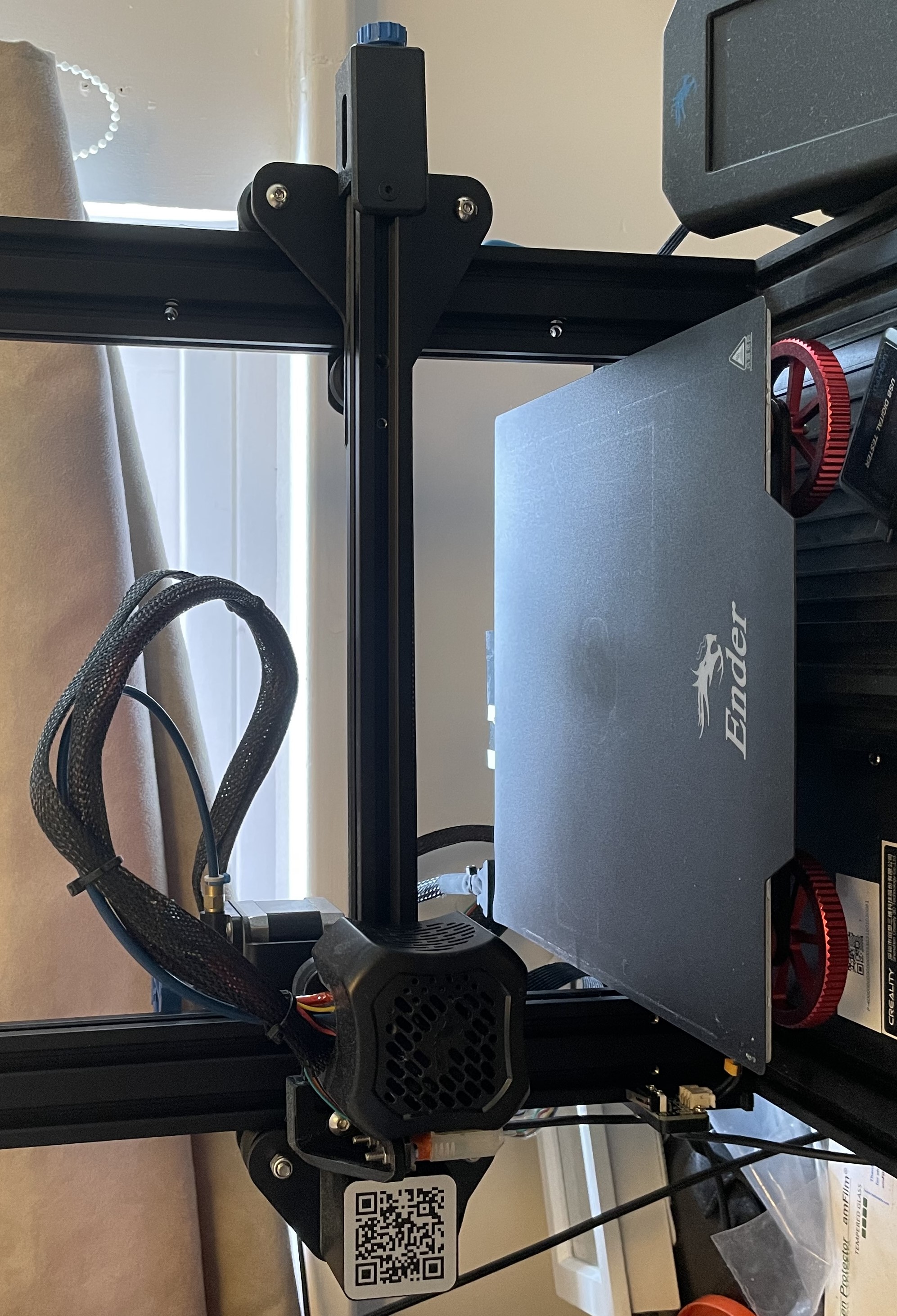
I have been a proud owner of an Ender3 v2 since 2022 and have loved building things and tinkering with it ever since. Prior to the extruder, I had made several improvements to the printer including a dual z-axis, a 3D Touch levelling sensor, and upgraded firmware. In my desire to chase faster, more accurate, and more exotic prints, I had reached a hardware limitation with the extruder that I could not overcome. Instead of hacking my way around the problem, I waited for a sale and purchased the fantastic Sprite Pro Extruder in a kit for my printer.
The choice to go direct drive, and an all-metal hotend, was due to the following:
- Better filament control
- Faster accelerations and higher jerk
- Shorter, cleaner retractions to reduce stringing
- Much improved ability to print with flexible filaments
- Easier filament loading/unloading
- Ability to print more exotic materials at higher temperatures
- Faster, more accurate, and more consistent prints
Installation
The extruder was a simple install, the included instructions were concise, and there were copious YouTube videos that could guide me every step of the way.

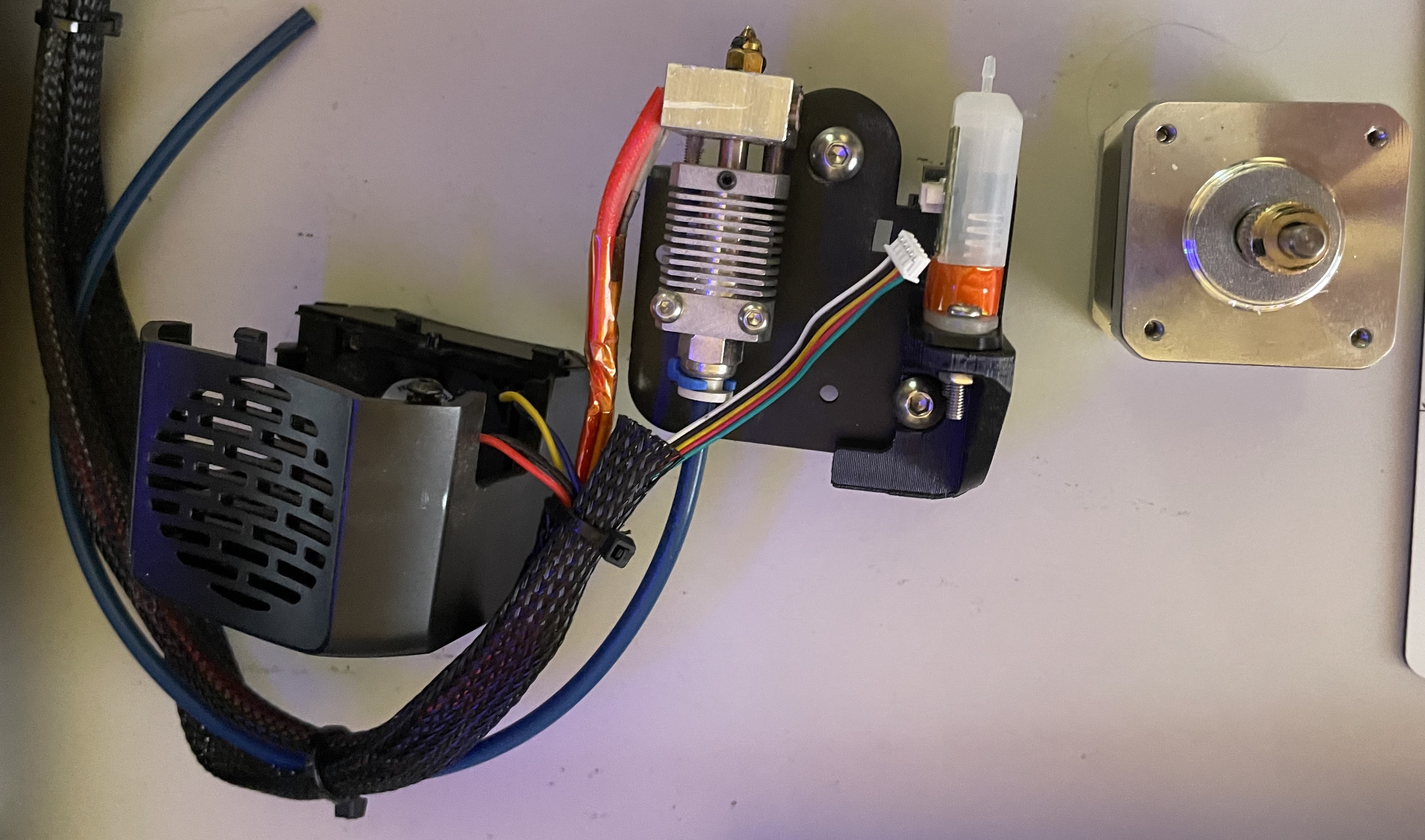
Getting the hot end off of the gantry was very simple: 3 bolts held on the plastic fan shroud, and with those removed it was possible to undo the nuts keeping the wheels secured. A little bit of jiggling to get the wheels around the extruded aluminium gantry and half of the extruder was disassembled.
The other half of the extruder, being a bowden setup, is on the far left of the gantry. Here, the stepper motor and extruder gears need to be removed. Again, a few screws, nuts and bolts hold this in place. When removing the exrtuder gears, check the plastic arm for any cracks. This is a common problem with these style printers and can cause extrusion issues, which is why a common upgrade is a new gear and metal arm. If the plastic is still in tact, the extruder can be reused in any other project you might want.

I still needed to removed the 3D touch sensor I had installed on the old setup. This sensor didn't come with a long enough cable, and the extension job I had done was not ideal, so I was more than happy to see this go when the new extruder (more on this later).
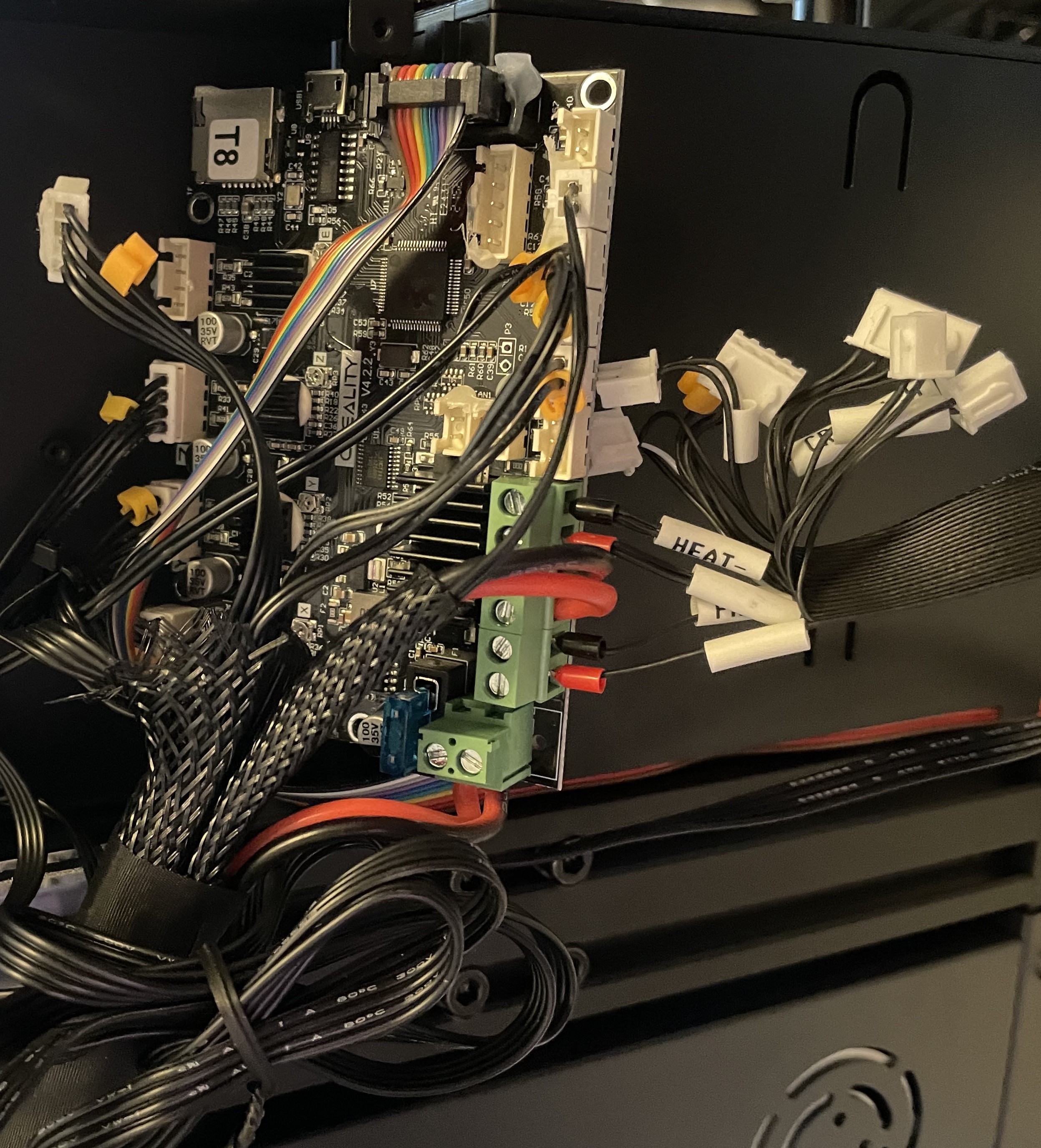
The final part of disassembly is to flip the printer over and unplug everything from the motherboard. I had been at the motherboard previously for the levelling sensor (and required version number when compiling the firmware), where I discovered that many of the hex bolts used to secure the board and the cover were very rounded off, and the included Allen keys were unable to get it open. I had read that using a Torx end can provide the grip needed to loosen off the bolts and it worked for me. I have since replaced all of the damaged bolts, but will forever rememeber that trick when I inevitably round one in the future.

Pretty much everything is well labelled and documented here so it's simple to rewire, but I still took a bunch of pictures just to make sure. Creality like to hot glue all their connectors to make sure they don't come unseated during shipping and operation, just make sure to remove any of this very carefully, as the plastic is very brittle.
From here you just feed the cables back through the cable sheath, cable tie it into place and start working on the hot end. I'd suggest getting the hot end mounted on the gantry first, before worrying about any more cables.
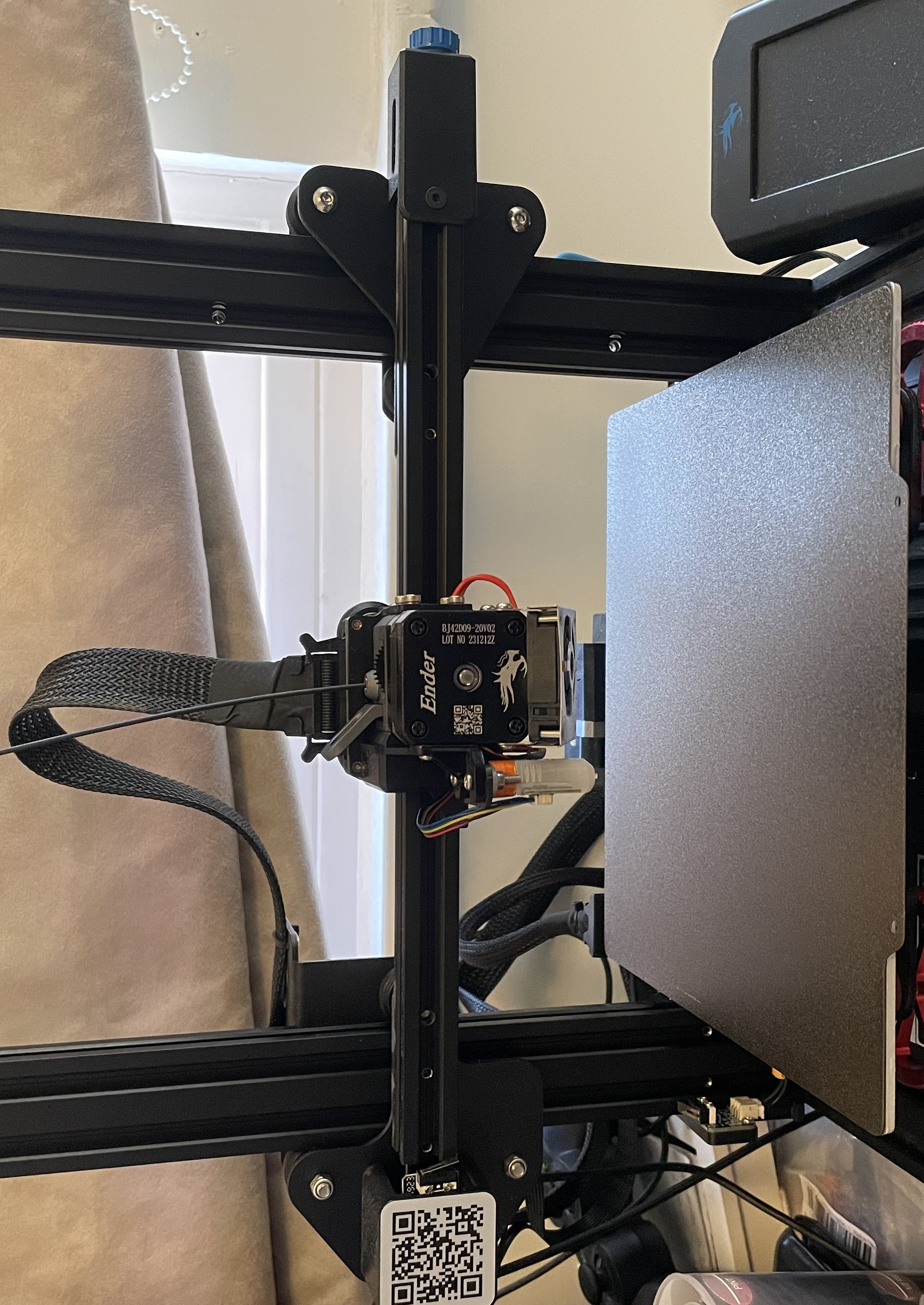
The hot end mounting is just the reverse of the removal. Once it was on the gantry I adjusted the eccentric nut until the carriage ran smoothly along the gantry. Personally, I would source some slightly shorter nuts here, as they currently touch the z-carriage on the right side meaning the levelling probe cannot reach the far side. It's not major, and you still get the full print length. The other major limitation is that the new extruder has an extended bit of metal to trigger the limit switch, but this is about 15mm further right than the previous hot end, so you lose some print volume there. You could look at moving the switch or cutting off some of the extension.
Next it was time to wire it all up. There's a single plug and connector which handles everything, and it's very easy to clip in. From here, I made sure that the cable had enough length to comfortably reach the far side of the gantry, then I cable tied it to the old extruder location (back left of gantry) to keep it out of the way of the print. I also mounted the 3D touch sensor. The new extruder comes with a very short cable for this, which plugs into the left side of the extruder (at the back close to the gantry) which is a much more simple solution than previously.

The final step was to update the firmware for the new setup. You'll need to measure the position of the 3D touch relative to the nozzle and add this in. The extruder instructions will give you a baseline for the new steps/mm value you'll need. You can also increase temperature limits for the hot end up to 300°C, and adjust any flow rate and acceleration limits for the hot end. Basic retration settings are also found in the instructions, but I would recommend running several test prints to tune in your parameters. I am currently running at 200mm/s with a 0.4mm nozzle and a 0.28mm layer height, and it looks fantastic!